Introduction / Clay in theory / Clay in practice / Catalog / Generic design / Reflections
5
GENERIC DESIGN
Introduction
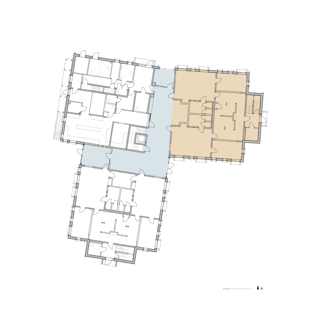
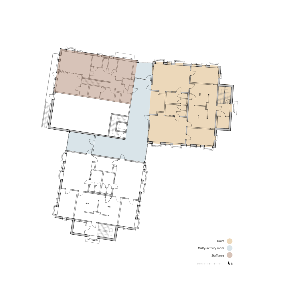
The generic design is applied to the Hoppet project that is used as a virtual testbed. It aims to test how clay materials can be implemented. In order to make this generic design development as relevant and interesting as possible, rooms of the Hoppet project were analyzed from an indoor climate perspective. In term of function, the units, the staff room, the common workshop and multy-activity rooms are identified as the most important and relevant to be studied from the indoor climate point of view, and the response will focus on these areas
TESTBED
AXONOMETRY
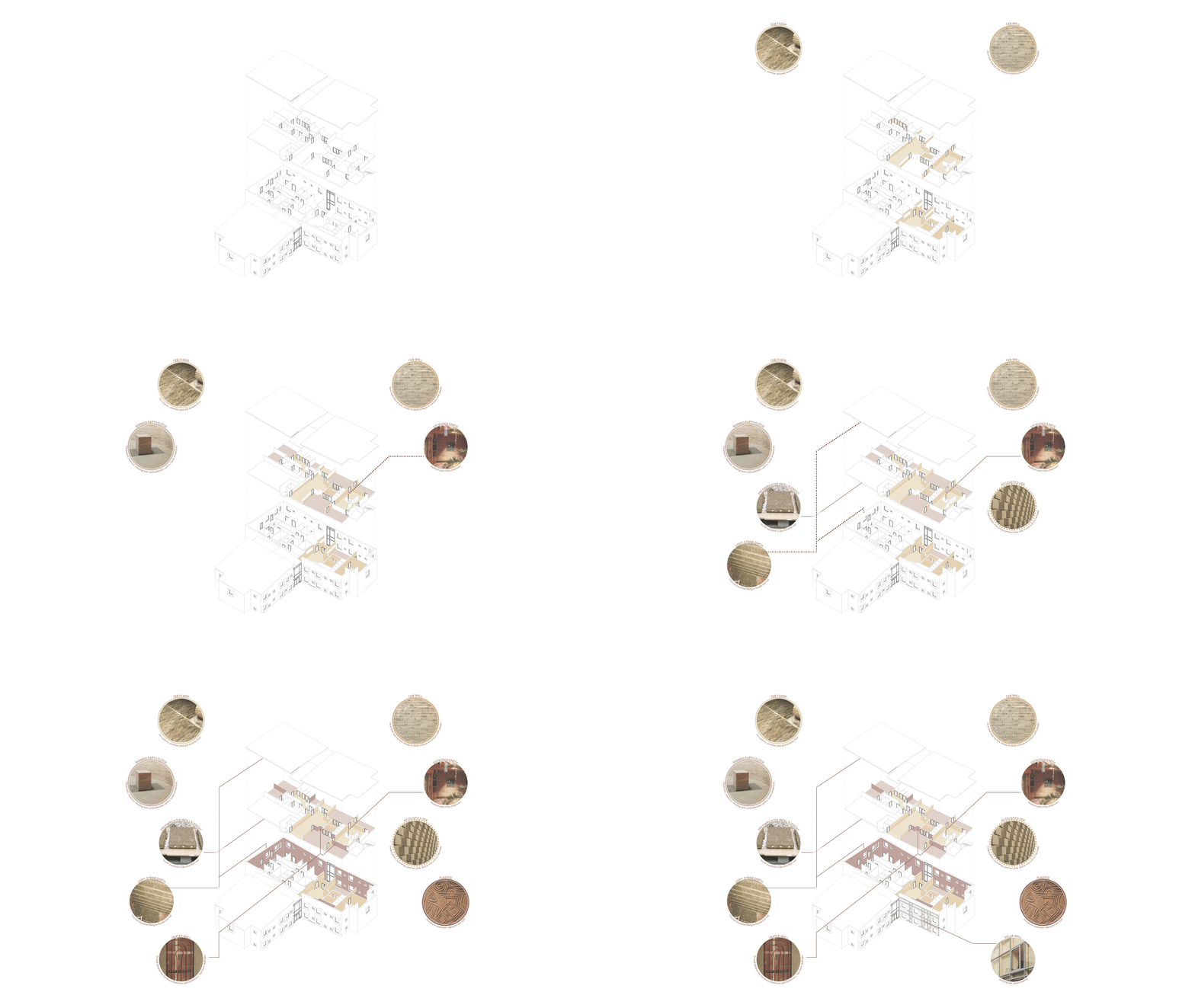
Testbed Axonometry
DETAILS
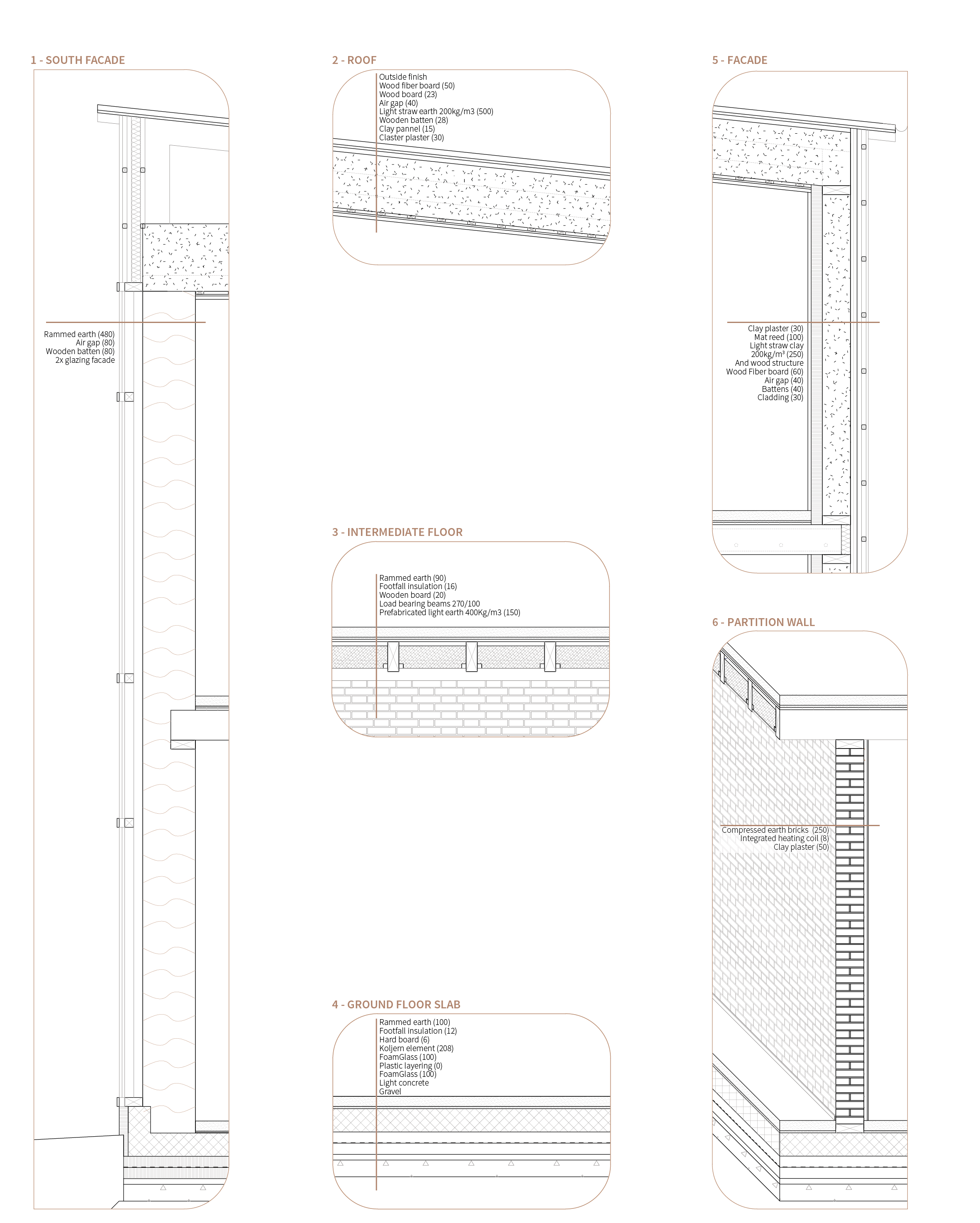
Detailed based on the previous testbed was developed and are presented below. It consists of conceptual details and the different layers of the proposition.
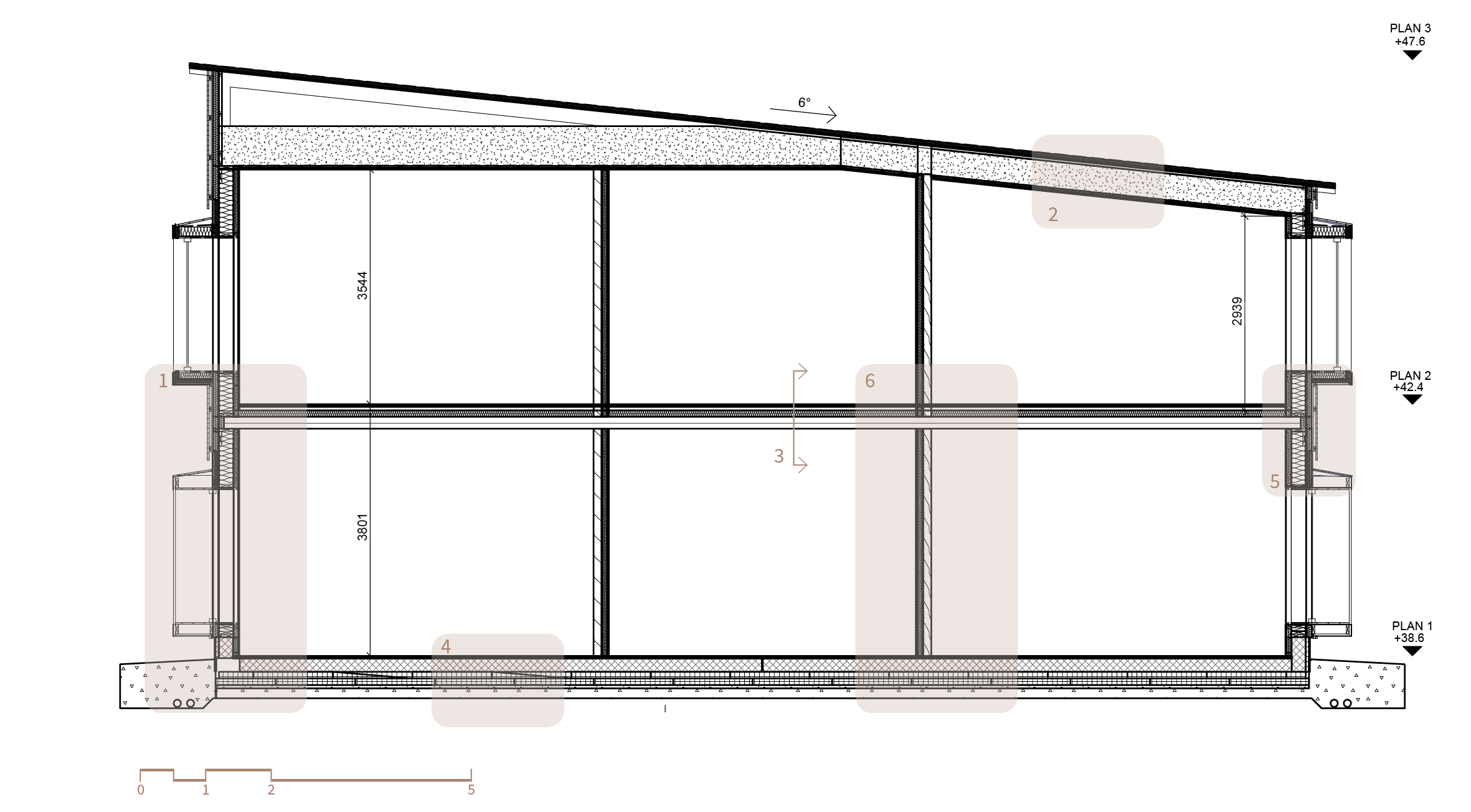
Hoppet Section (Architects: LINK Arkitekture, Constructor : WSP)
IMPACT ON INDOOR CLIMATE
The proposition aims to improve indoor climate comfort, and below are presented schematic sections that show how the clay implementation impact and improve the climate in winter and in summer.
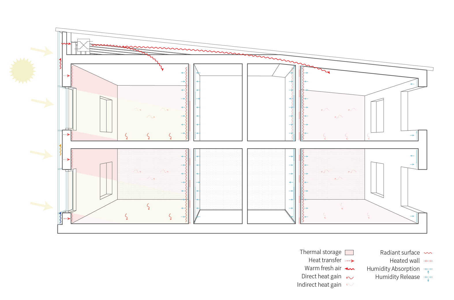
In winter, the solar façade on the south wall uses the greenhouse effect: the fresh air is pre-heated between the glass and the rammed earth while going up toward the ventilation system to be distributed in the building. Thus the full building can benefit from the façade and not only the room connected.
The clay screed flooring is used for its thermal mass, it can store the direct heat gain from the sun or the indirect indoor gain.
Finally, the CEB wall between the bathroom and the classroom is visible from the bathroom and covered with plaster and heating coils toward the classroom. It combines the heating system with the thermal mass of the brick and therefore optimized the system. The clay plaster also applied on the northern facade improves the humidity and acoustic regulation in the classroom.
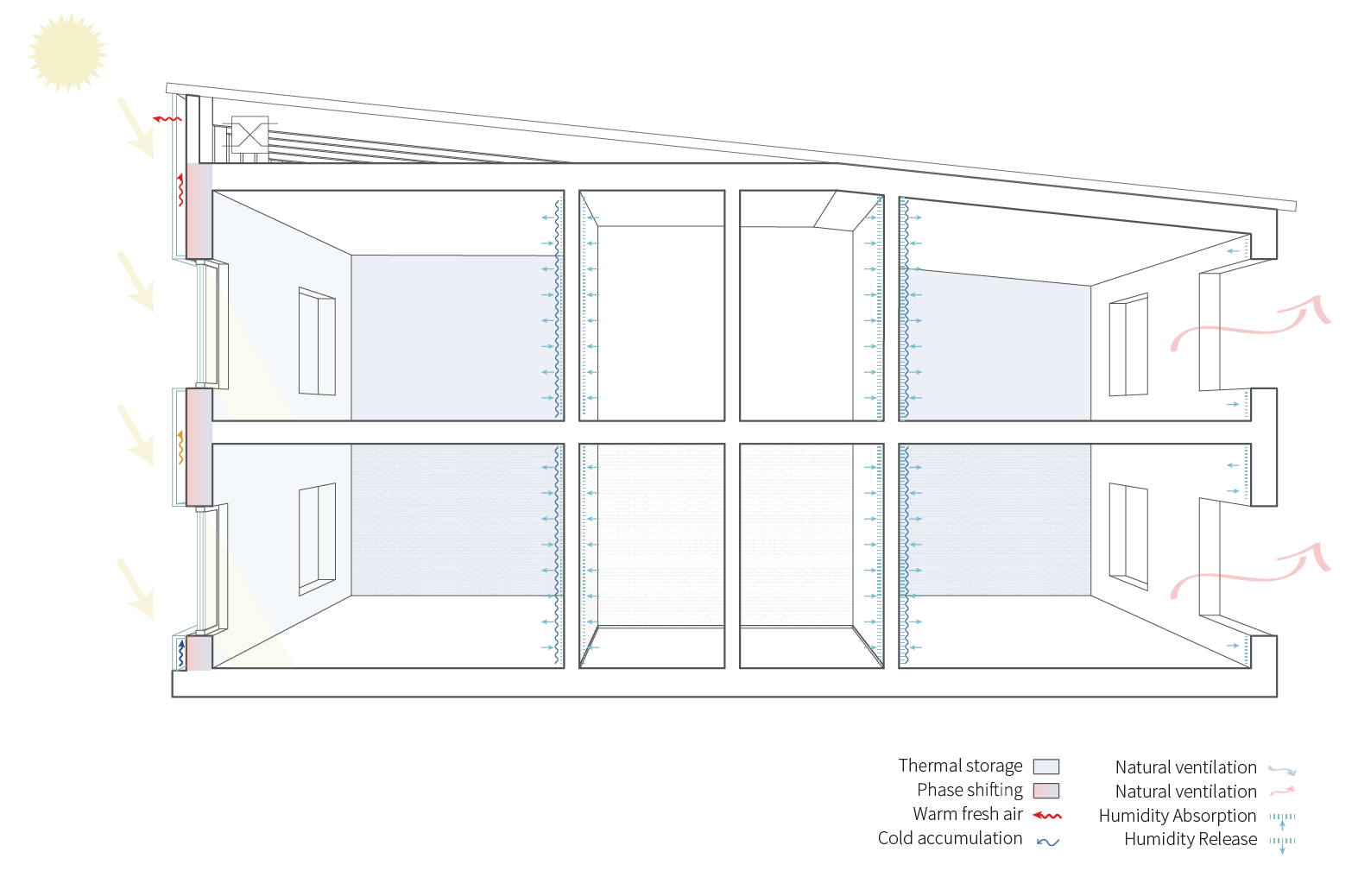
In summer, air circulation is created in the façade to avoid the storage of heat, and the connection with the ventilation closed. Thanks to the phase shifting of the material, the thick wall would release the eventual daytime heat accumulation at night, and can at this moment be easily dissipated with natural ventilation.
The clay floor screed can store the freshness of the night and diffuse it slowly during the day.
LCA COMPARISON
A comparison between the testbed and the original Hoppet project was done with the program PHPP. It compares the emissions the storage balance, and the U value of both propositions. Generally, the emissions are lower for the testbed than for the original Hoppet project*, except for the facade: due to the glass whose production creates a lot of emissions. This impact could however be reduced by reusing old windows from a demolished building. The original Hoppet project uses a lot of wood and therefore has a high storage balance compared to clay materials. Clay has a CO2 storage capacity only when mixed with straw. This point underlines that it can be interesting to use wood and clay in synergy. However, the most sustainable approach is probably to reduce emissions as low as possible rather than trying to compensate them: the day it will be possible to produce without emissions, it will no longer be necessary to compensate them.
Finally, the U-value is worse with clay. Thus, a balance must be found between the CO2 emissions linked to the production of the material and that linked to the building’s heat demand. A more in-depth study to compare the energy demand of this solution could be interesting in another study.
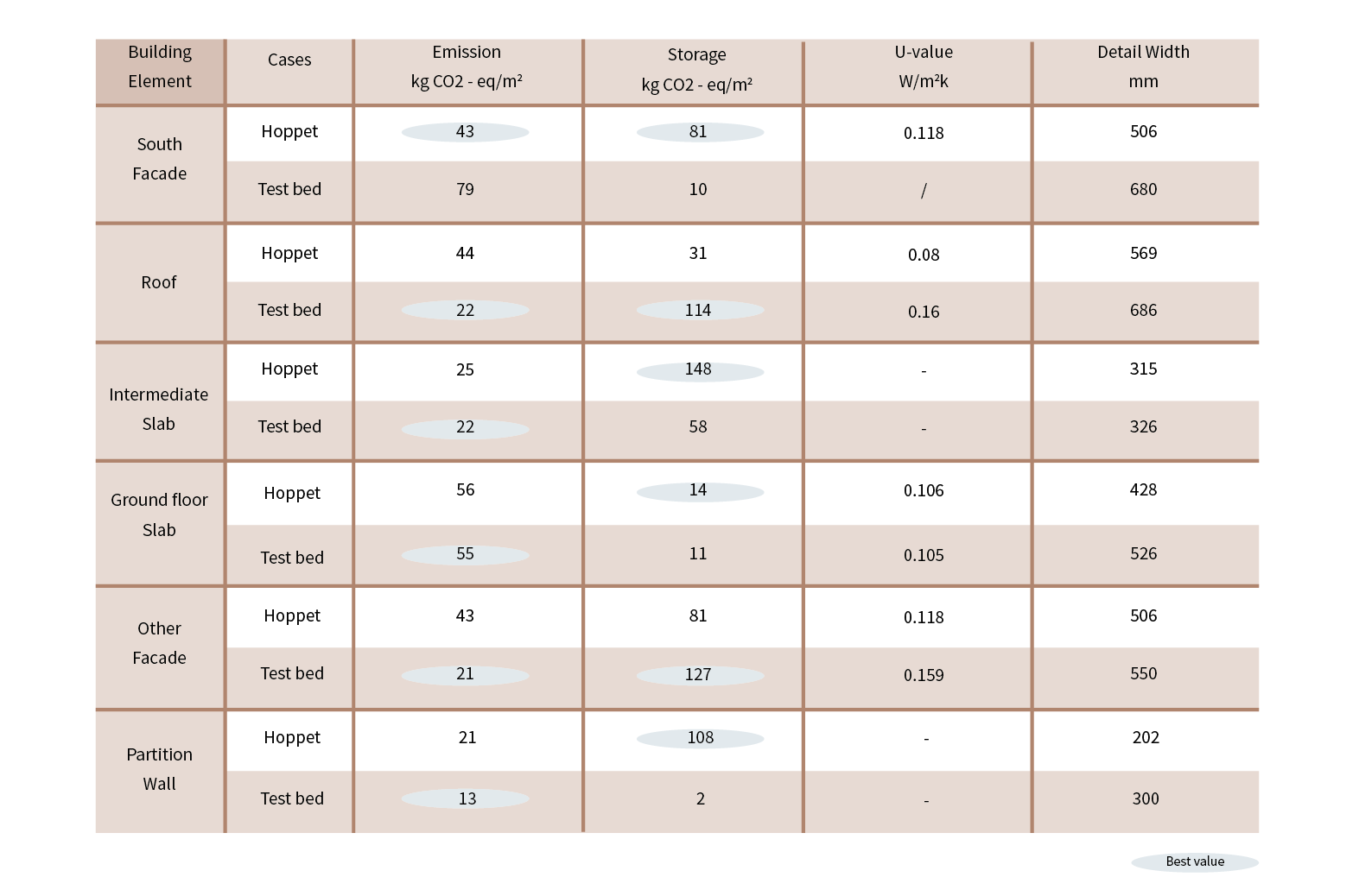
Hoppet and Testbed proposal comparison on LCA and U-value*
*It is important to point out that the kg CO2-eq values presented here, calculated with PHPP, are not exactly the same as those calculated by Derome (Calderon R., Ryberg A., 2021), stakeholder in the Hoppet project. Nevertheless, the range of values is similar. This difference can be explained by the fact that the different softwares index their calculations on different reference values depending on the material bank. However, in order to compare them in the best possible way, I used in both cases the value that I calculated with the predefined PHPP material list.
FROM GROUND TO BUILDING
The diagram below explains the different steps that would be necessary to build with what is under our feet. There are several steps to follow that can be done on the construction site or in a production facility set up within a short radius perimeter. Mapping, testing, and prototyping on the resource are important steps in the process to know whether or not it is possible to build with it. It is also important to determine early the type of materials made of earth in order to know the necessary characteristics of earth for its implementation.
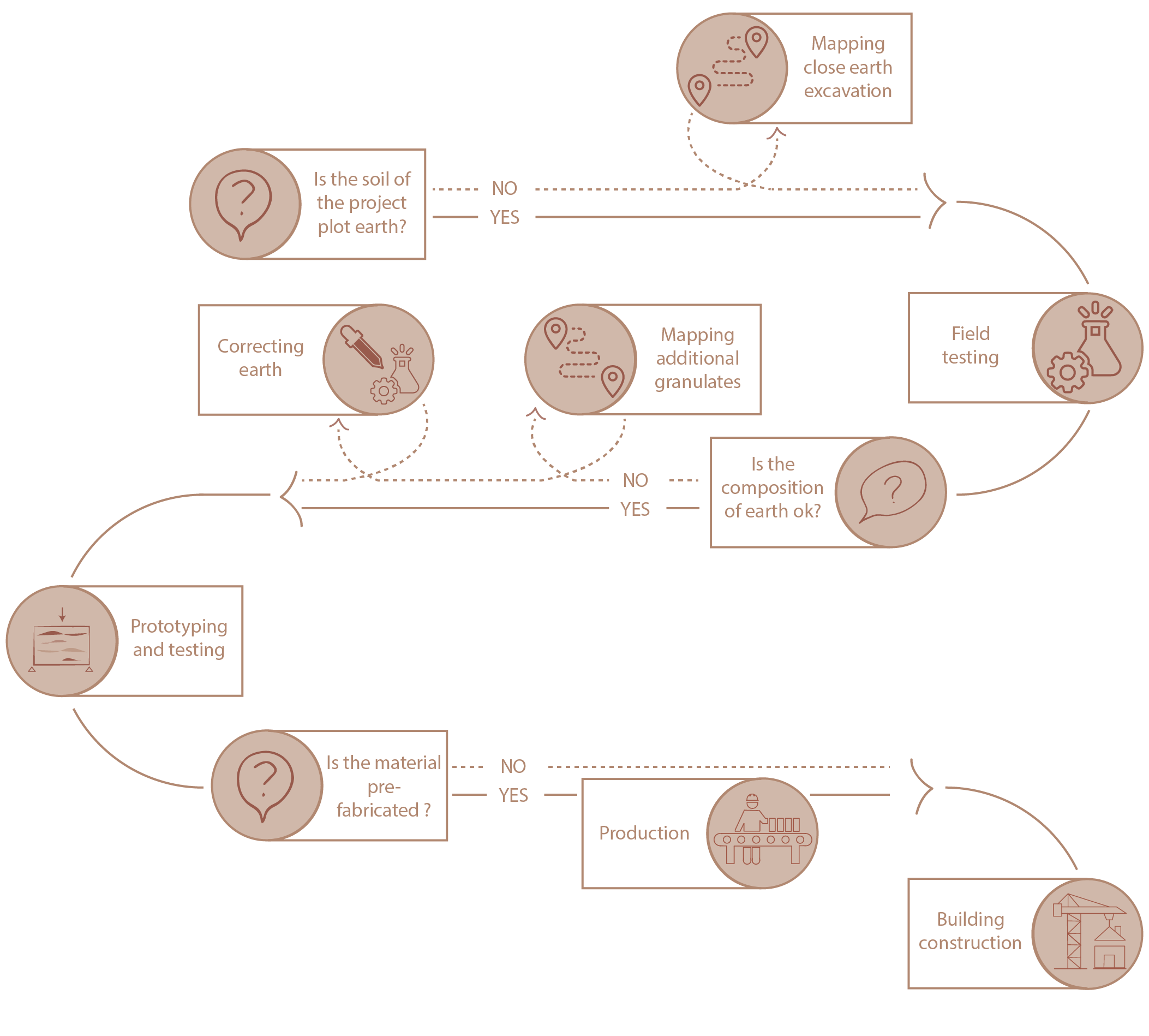
Process from ground to building
In Göteborg, as explains in the theoretical part of the research, a lot of excavations are underway to build new infrastructures such as the Väslänken underground or the development of the northern district of the city. These worksites are potential excavation sites from which clay could be extracted. The sample previously tested in the master’s thesis comes from the extraction of the Mariholmstunneln, a newly constructed tunnel under the Göta Alv. This earth is very fine loam according to the test results. In order to make the rammed earth wall of the testbed, it is necessary to have larger aggregates in the mixture. Therefore, if the earth previously tested in this master’s thesis were to be used for the testbed an addition of sand and gravel would be required. The resource mapping below points out a sand and gravel quarry near Landvettersjon, about 15 km from the Hoppet site, remaining within an acceptable perimeter for local resources.
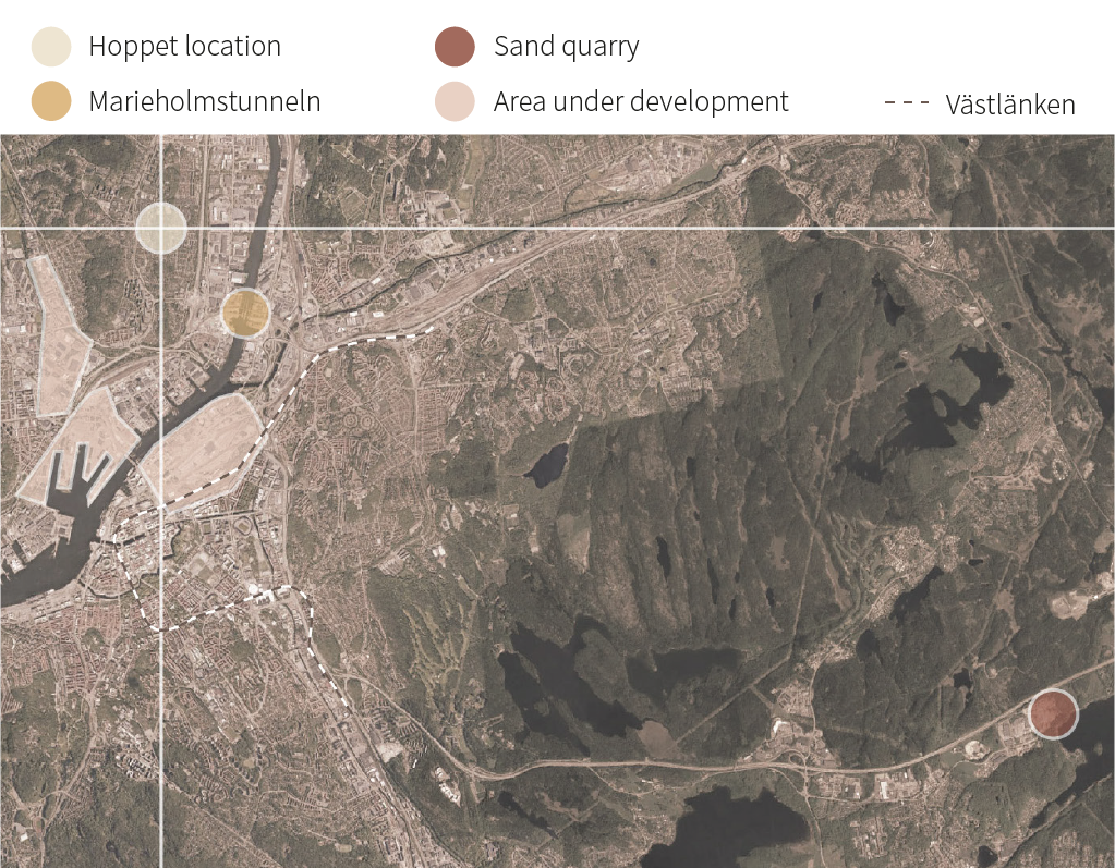
Resource mapping

