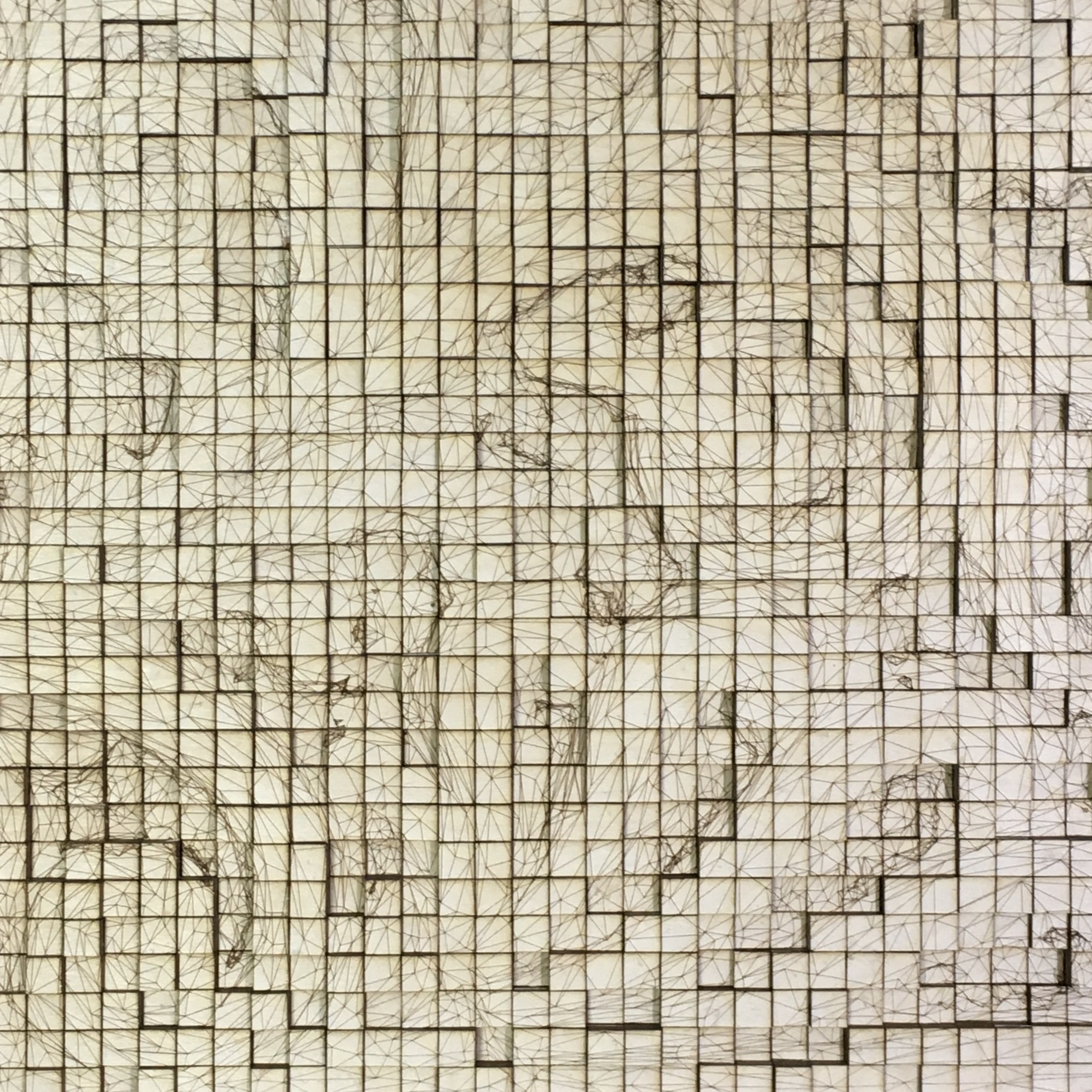
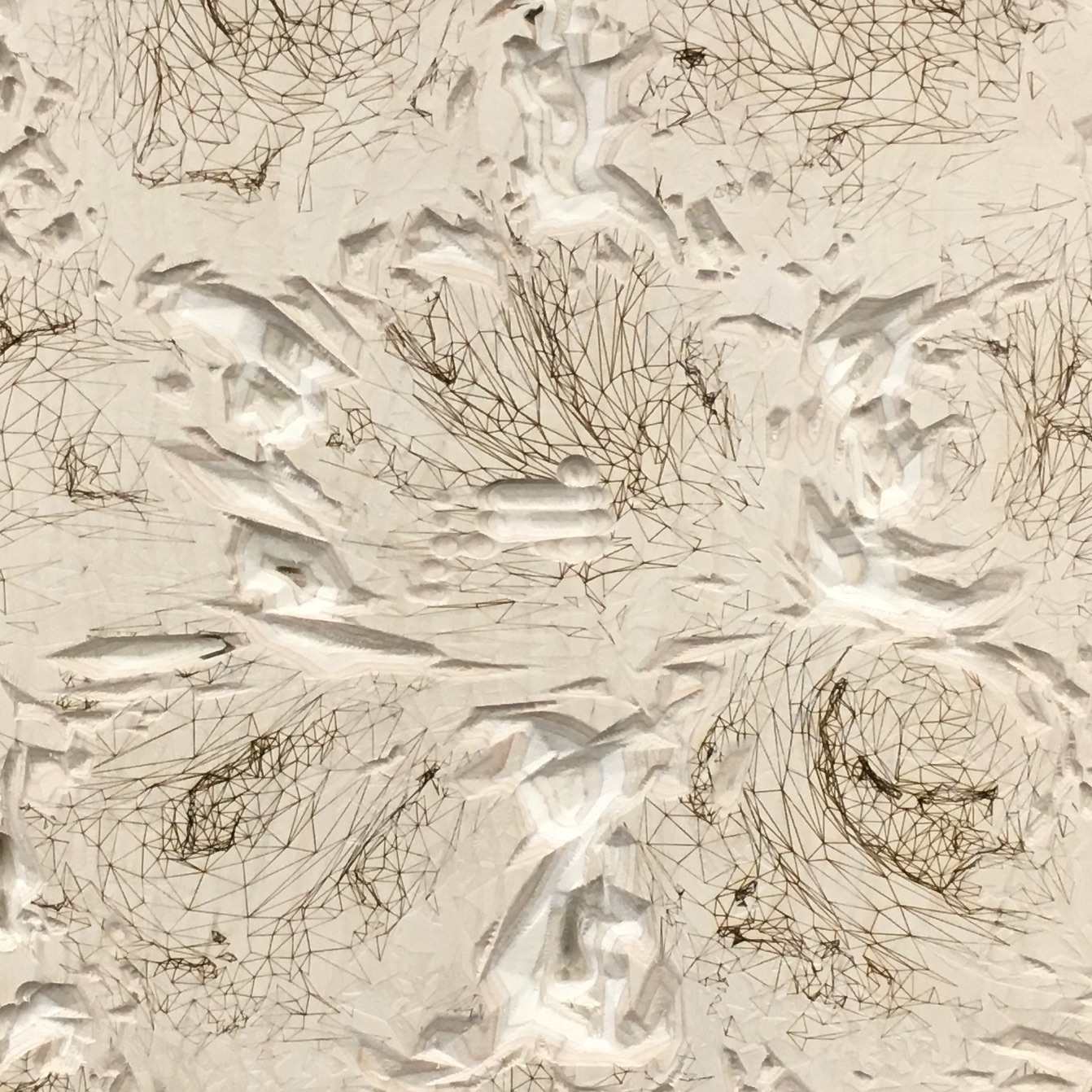
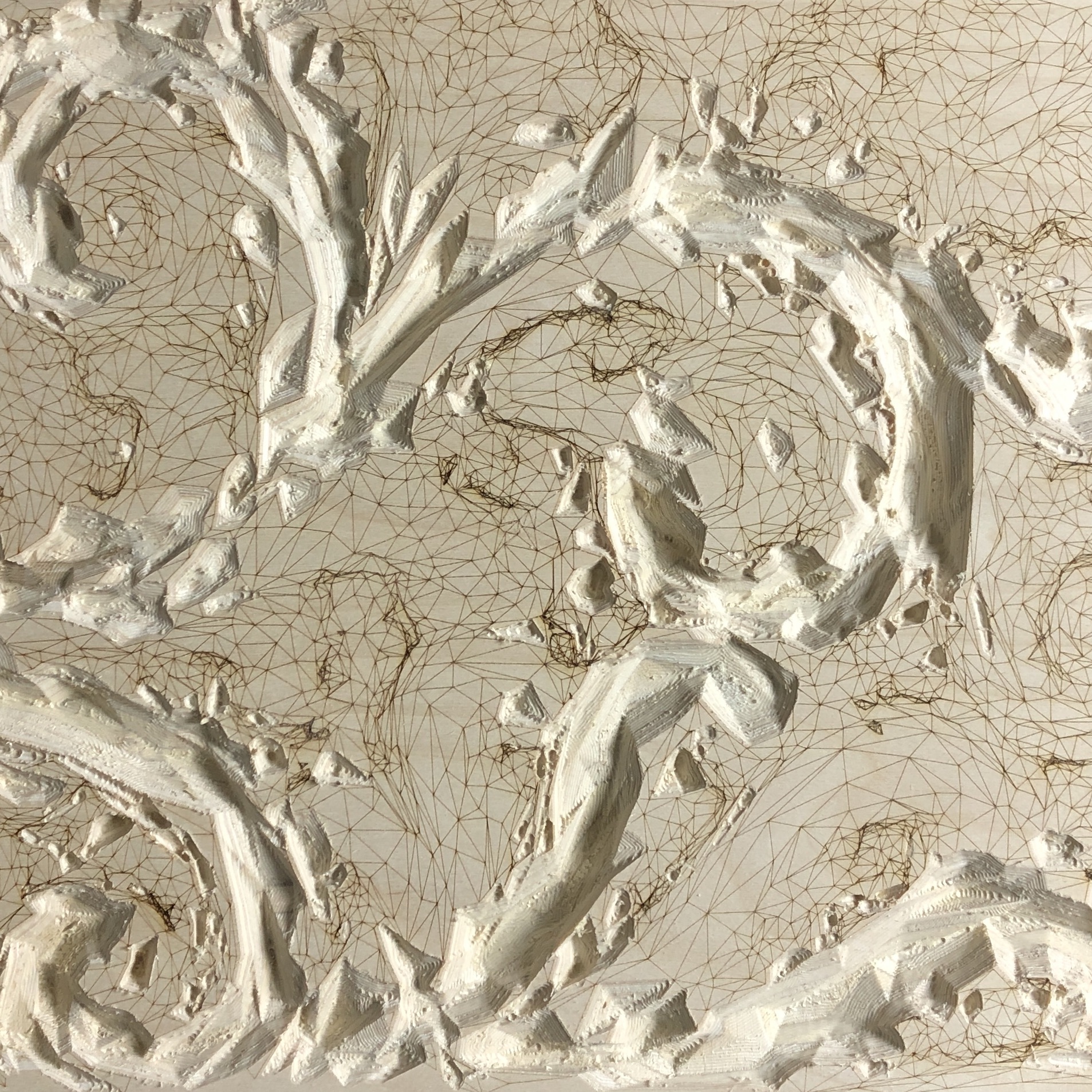
5B. 2D/3D Projection
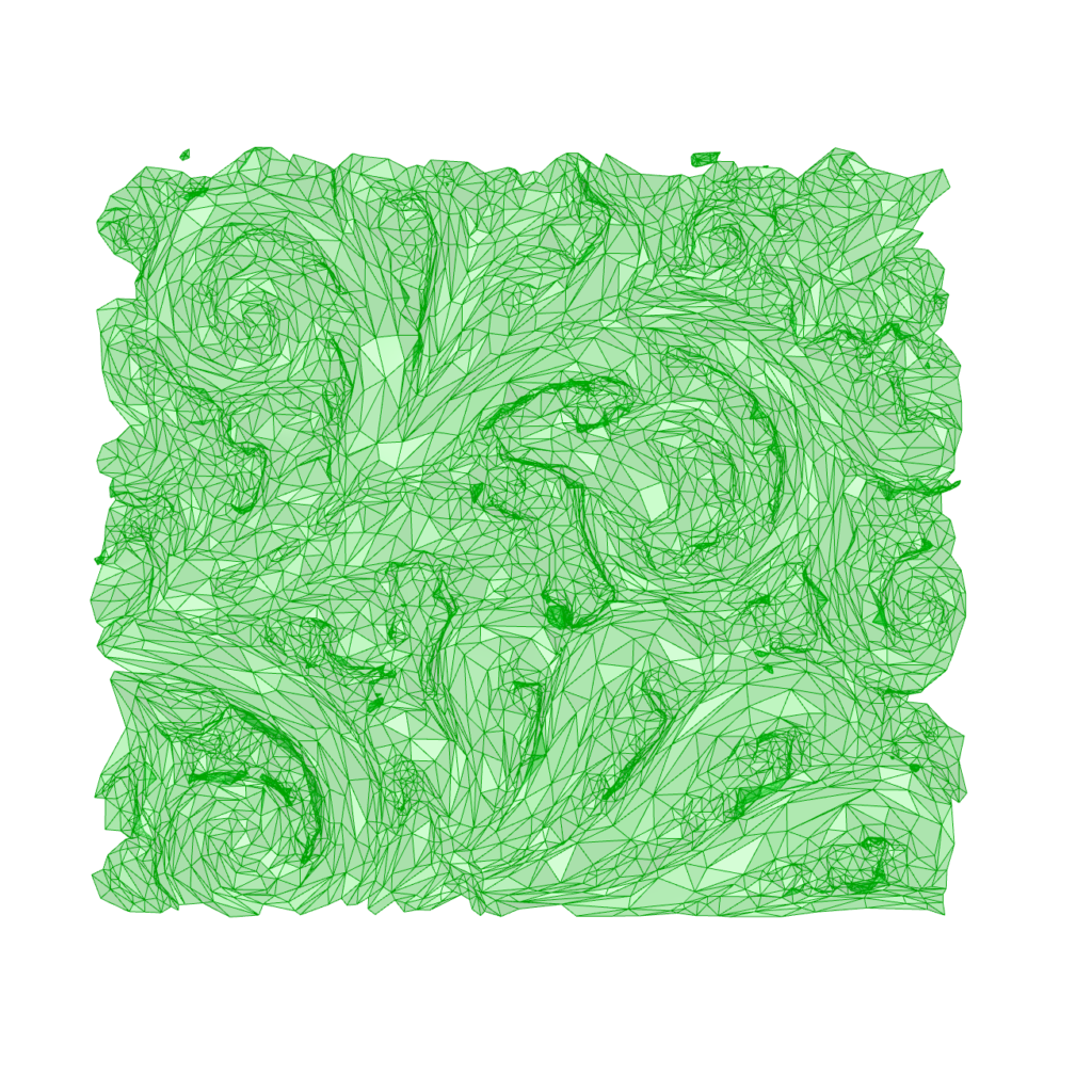
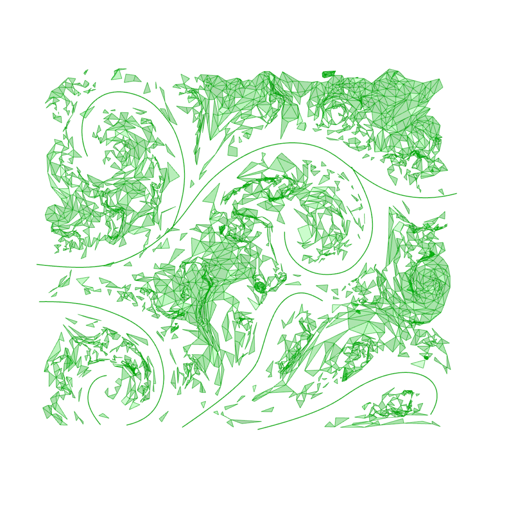
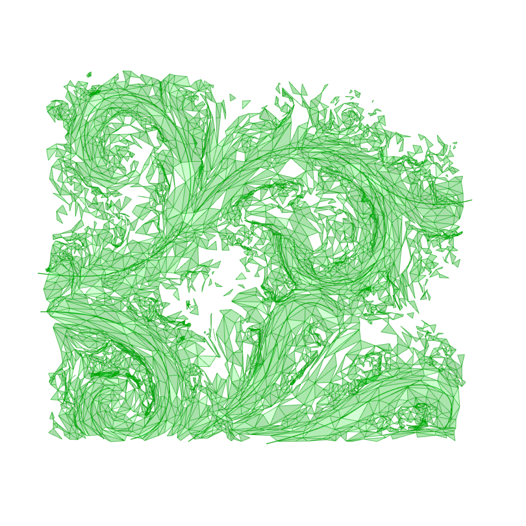
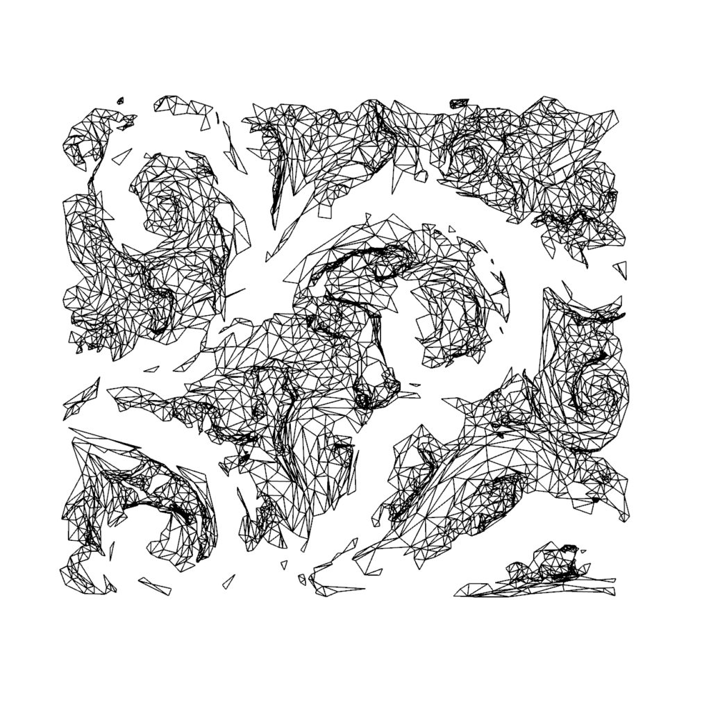
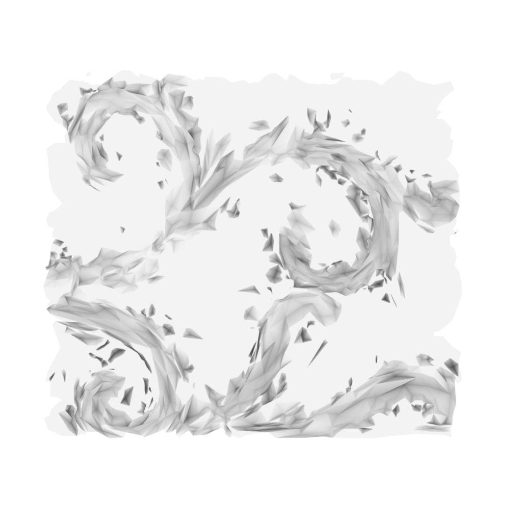
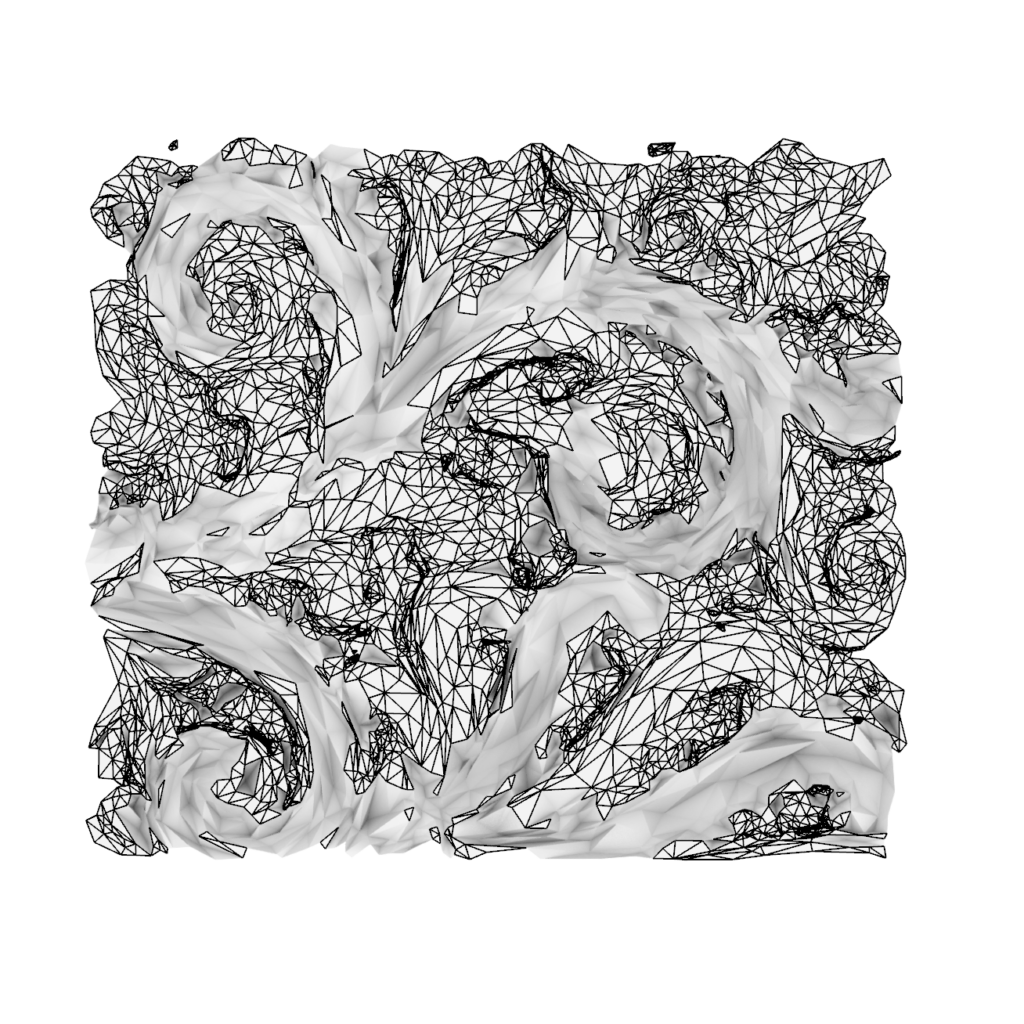
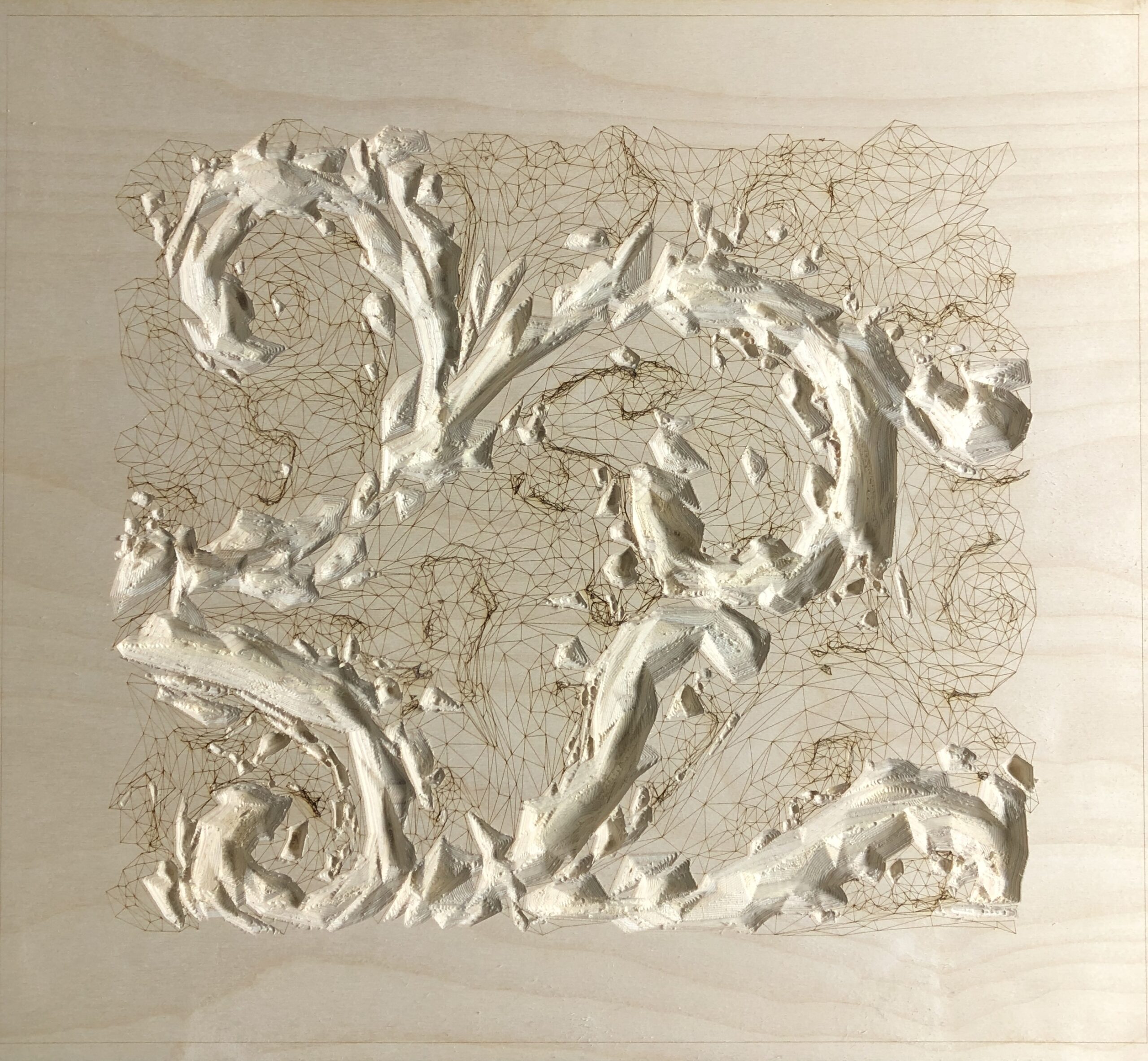
To further test the concept of Ornament 5A, a smaller segment of the mesh was selected and processed using a similar design strategy. This time however, to better respond to the original expression of the geometry, curves instead of points was used to reduce the mesh.
Method
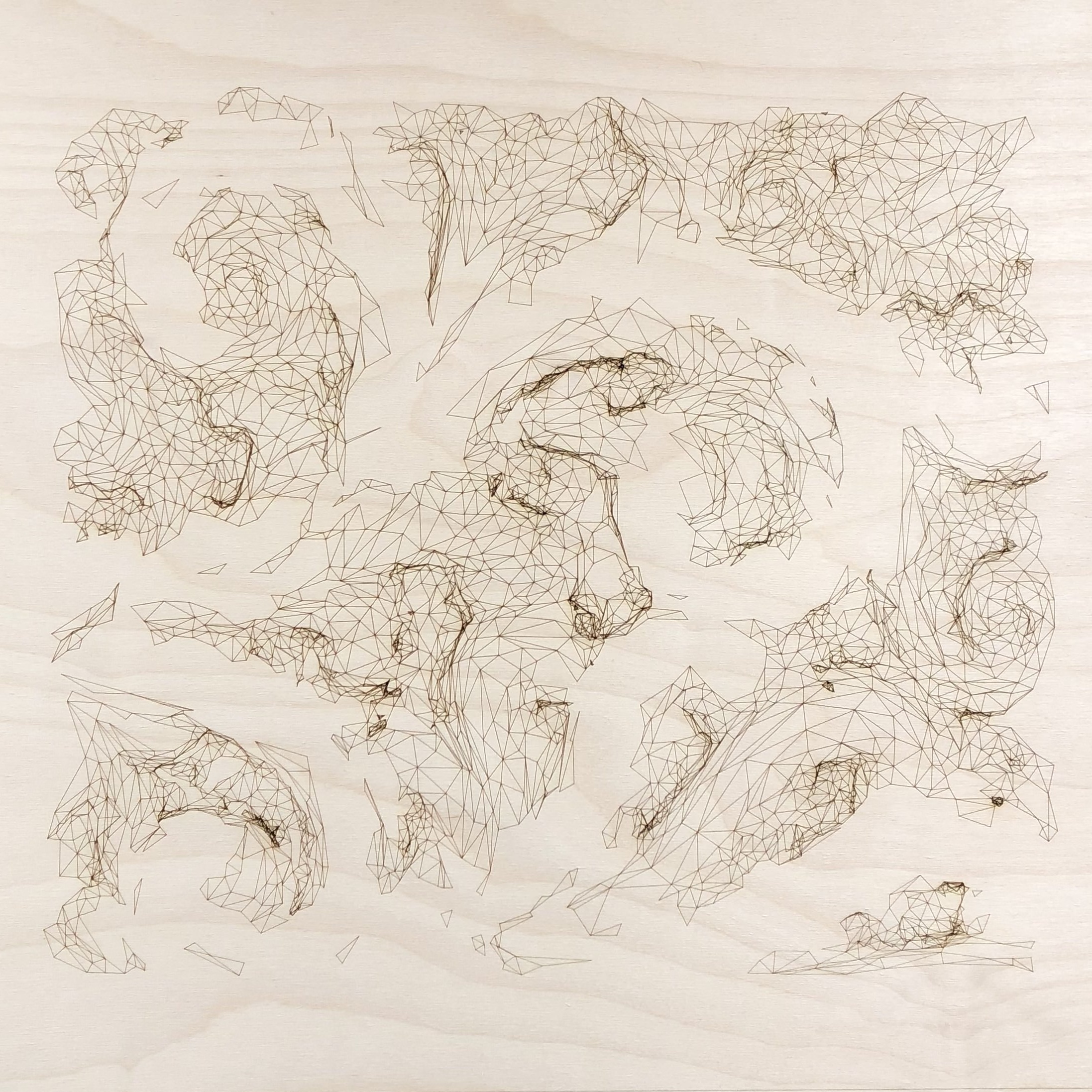
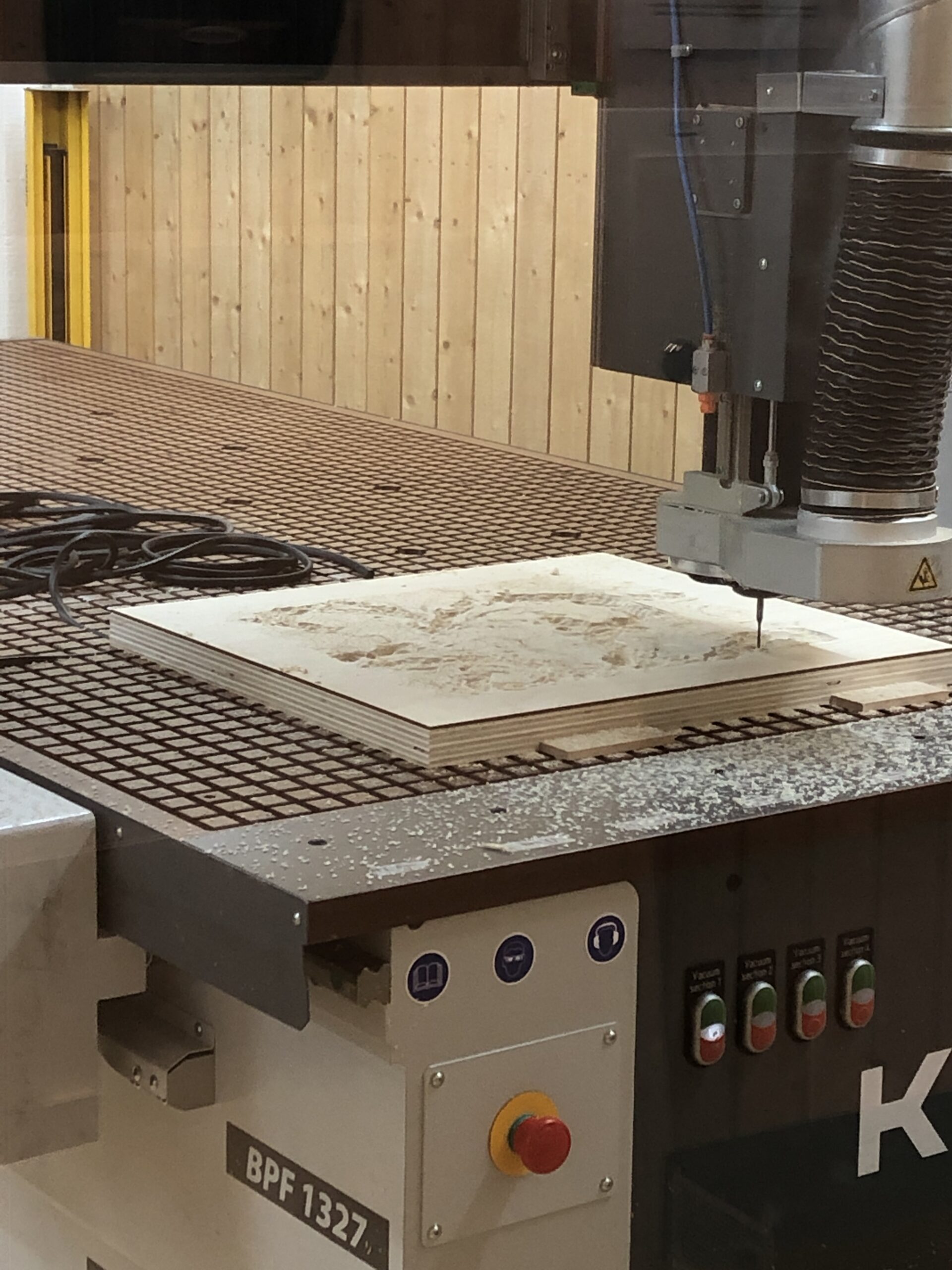
The guiding curves where manually drawn on top of the original mesh. In Ornament 5B, tweaks were also made to the linear expression used to divide the mesh into its engraving/milling to create a sharper boundary between the two fabrication methods. Apart from these changes, the digital and physical workflow was kept as in Ornament 5A.
Result and discussion
The mistakes made in Ornament 5A were avoided when making Ornament 5B. The inclusion of lines rather than points made the design process of this piece very different from the previous one. Mostly in that it was much easier to guess what a given curve would mean to the splitting into engraving- and milling-sets respectively. The “free-hand” feel was therefore more prominent when creating this design. It would nonetheless be interesting to test this workflow on several different scans so that the script could be more precisely developed to allow for more control over the outcome. Again, the unavoidable discrepancy between the digital model and the physical outcome could through more experience help guide the design process further.
