Kinetic System
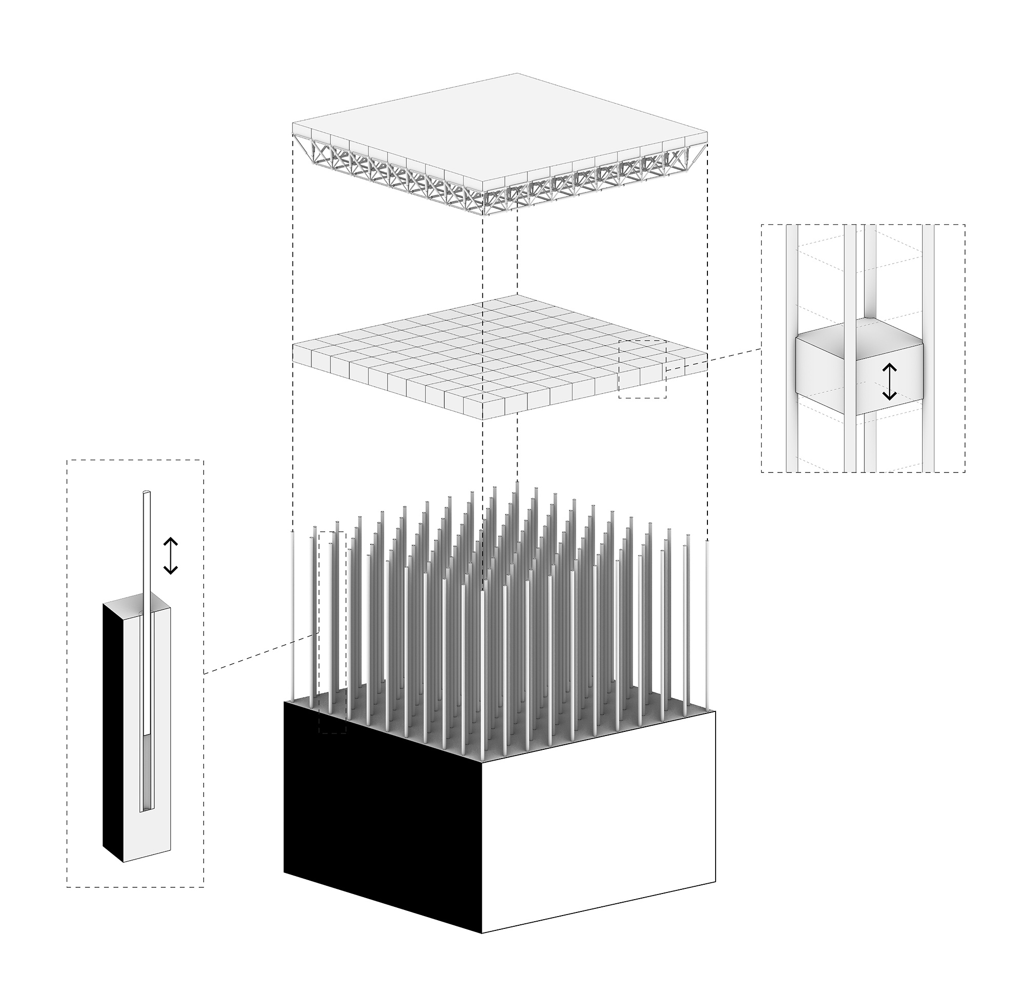
The structural kinetic system involves two layers of separate mechanisms working together to make the system as flexible as needed. Making it possible to transform a square into many different shapes and functions. Each system has its own limits to what it can achieve which in return determines the limits of the entire design and the whole system. The top layer and the main system for the transformations is the kinetic space frame, with actuators changing length and rotating freely in every connection point.
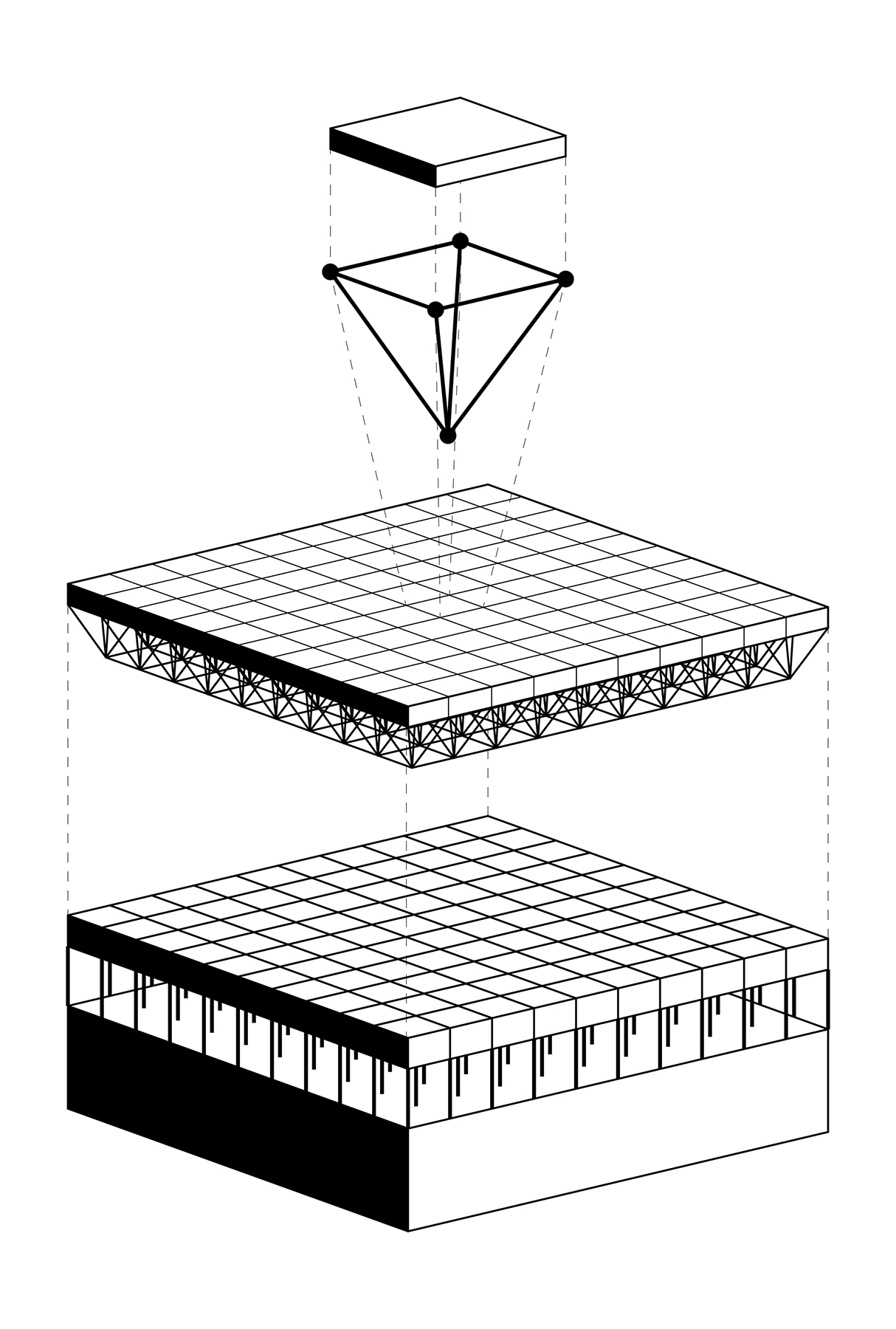
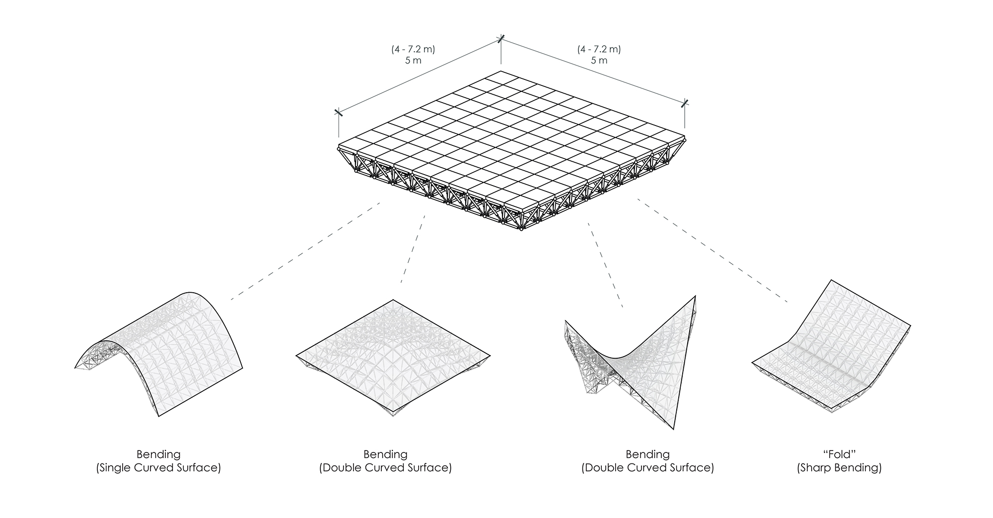
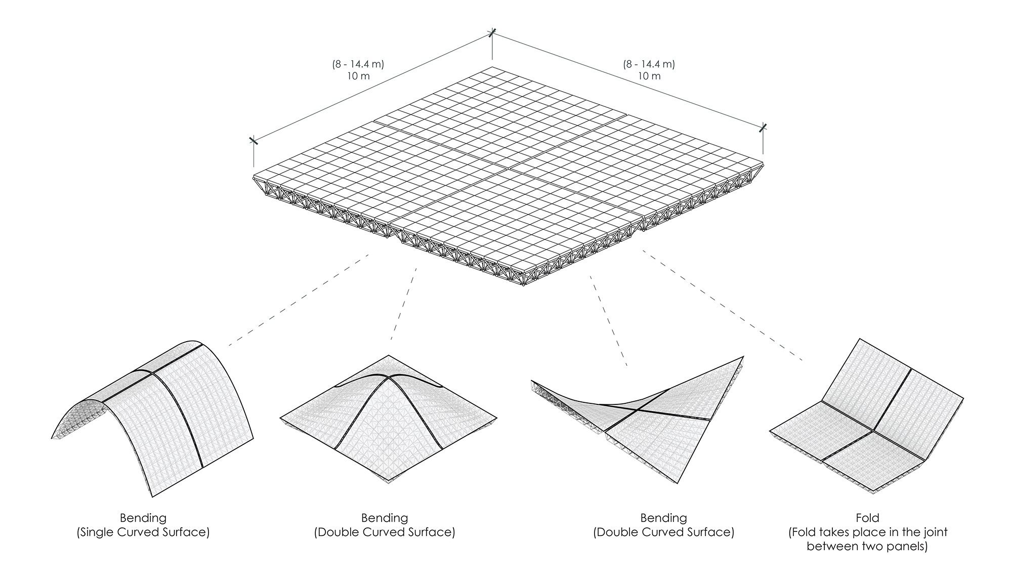
The layout of the public square is divided into a grid of 5x5m panels that forms the surface of the square. These panels are then divided into a 10×10 grid which forms the outer grid of the space frame. With each actuator in that grid having the length of 0.5m in a flat condition and the ability to extend to even longer. Each of these squares in the 10×10 grid creates the basis for an upside-down pyramid, with all the centre points connected creating the inner 9×9 grid.
Actuators & Joints
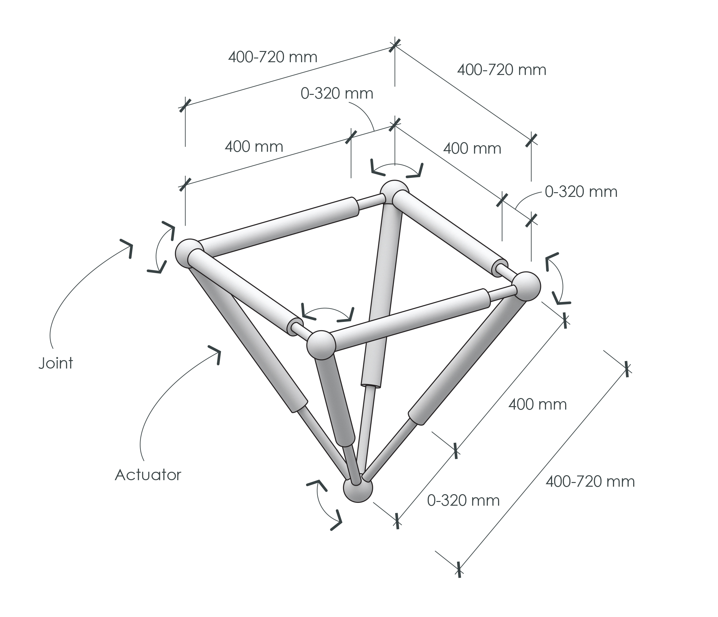
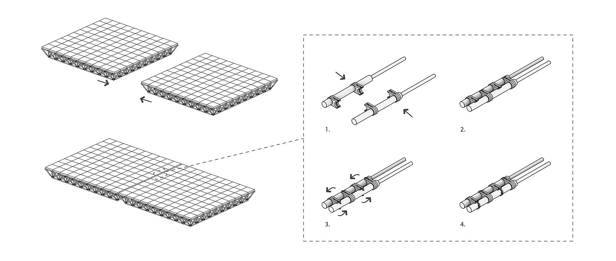
To make the entire system kinetic, there are two elements needed, the joints and the actuators. In this system the actuators are hydraulic cylinders that can individually extend and retract themselves, changing the length of every single line element in the space frame. However, if one changes so will another, so the change must be controlled over the entire system. Creating a space frame system that can act and behave almost as a flexible surface with abilities to bend and fold.
Since each actuator in the system has a limit to what it can extend or retract to, this also creates the limitations for the entire system. The actuators in this example are dimensioned with the fixed element as 0.4m and the extension ranging between 0 – 0.32m. This means each actuator in the system can fluctuate between 0.4 – 0.72m.
To make a fully kinetic space frame like this, the joints need to be as flexible as possible. Each joint has several links connected to them that needs to rotate freely in all directions. This makes the joints the most complex piece of the structure and are therefore simplified with a simple sphere in the models. However, a spherical joint can only handle two links in the way needed for this system.
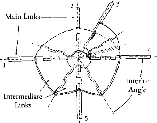
There have been several attempts to create better spherical joints that can handle multiple links. In 2003 Bosscher, P & Ebert-Uphoff, I proposed a spherical joint mechanism with the ability to rotate several links around one centre point.
Columns & Floor Panels
The second layer in the system is a simple kinetic mechanism of floor panels and columns. This layer is also divided into the same 10×10 grid as the space frame above, with a column in each intersection. These columns can rise and be used as support for the kinetic space frame, turning the space frame into a roof system. Since the space frame can be moved out of the panel, there needs to be another system functioning as a floor for people to walk on. This is the main function for the floor panels in this layer, they will individually move up and down on the columns as rails and fill in empty spots when the space frame has transformed.